
BIM – Definition – What is BIM?


BIM or « Building Information Modeling » has so many definitions it is almost ridiculous. Some don’t even define BIM as « Building Information Modeling » but rather as « Building Information Model » or « Building Information Management ». Many organizations, software editors and individuals claim to be the « true inventors » or « true initiators » of BIM. Some insist they were the first to know about BIM and know best how to use it.
So what is BIM ?
God forbid, if you seek the answer in Wikipedia, you’ll most probably regret it. It fails to explain this multi-faceted and vast concept and settles for a bland, general and vague definition of what BIM is.
Luckily, BIM is actually something quite simple to grasp if you’re an AEC manufacturer. Most existing BIM ‘explainers’ are directed at architects or at the clients of building projects. In this post however, I’m going to explain what BIM is from the AEC manufacturer’s point of view.
The easiest way to quickly grasp what BIM is, is to first understand what a BIM object is and then understand what this kind of object is good for, and the best way to understand it is:
A BIM object functions as a recipient
And here’s a picture of a glass of water to help you remember it:

The glass itself represents a 3D model or any other kind of what is commonly called « Geometry » which basically means a 2D or 3D shape of SOMETHING
The water inside it represents INFORMATION ABOUT THE SOMETHING
And as you can see, the « water » adopts the shape of the object it is contained in. That is it. Simply put, a BIM object is a 3D geometry that contains information about it’s essence.
Now, if you are an AEC manufacturer all you have to do is imagine one of your products instead of the glass of water shown above. Your product could obviously be described geometrically (i.e – modeled in 3D) and you could probably also say lots of things about that product of yours. Let’s imagine for the sake of the example that your product is an automatic door instead of that glass:
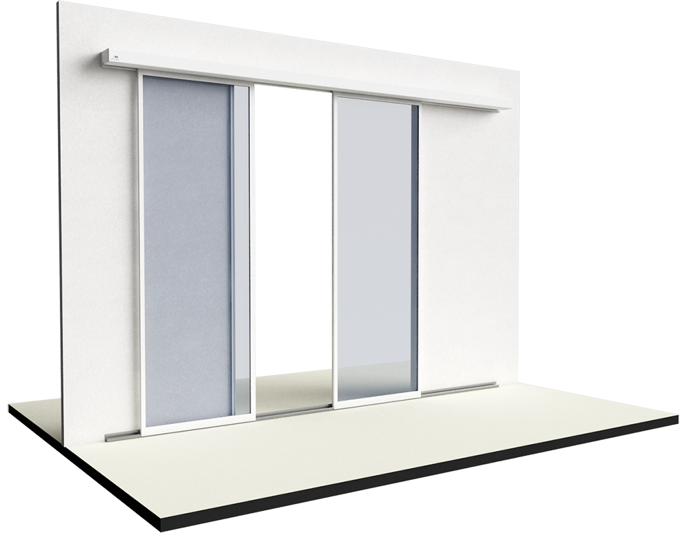
This door has a certain shape, a width, a length, a thickness and several parts – this is its GEOMETRY.
It probably comes in different sizes and proportions to fit different types of openings – this is PARAMETRICAL information.
It also has different materials, (wood, metal, rubber, trans-lucid or transparent glass, plastic etc.) It replies to some norms and standards and is classified under a certain reference or catalog number. It is also manufactured by someone (you) and you have a phone number and an address where you (or your sales / technical force) can be reached. All of this is essential information.
If this automatic door is a BIM object then all of this information (parametric or not) is simply INTEGRATED into the geometry of the 3D object.
You probably understand by now what all of this is good for. The ability to integrate information into a parametric 3D object is a great thing. It allows the architects and any other AEC professionals (quantity surveyors, engineers…) involved in the conception of a building – to conceive a building with hundreds of such intelligent « building blocks ». Each block is « self aware » of what it is and each interacts with all the other elements of said building. For example, this door integrates into a wall somewhere in the project. The wall itself contains information about its thickness, it’s function (supporting or just separation of spaces) insulation, the dimensions of its openings etc. The wall might be « sitting » on a concrete slab covered with tiles of a certain shape and color etc etc. All of these BIM components together make a BIM MODEL and this intelligent BIM model is the basis to what BIM is all about.
Because, as soon as you have a BIM model, you can do many things. First, YOU CAN EDIT it really easily. For example, if you have a staircase in between two concrete slabs and you decide that you want the room’s ceiling to be higher all you have to do is increase the distance between those two slabs of yours, the staircase will respond automatically as it « knows » that it is connecting two floors and the BIM object that is this staircase will add extra stairs to itself and an extra length of railing to go along with it.
Second, this magical BIM model can provide you with tons of useful information that YOU CAN QUERY with a few clicks. In most BIM software you can get a detailed listing or nomenclature about all of the components that make your building. Not only how many square meters or yards it has but also how many doors, windows, chairs, and lamps it contains. This of course is very helpful if you’re an architect or a client.
If you are the person in charge of the maintenance of the building that is going to be built you could easily know how many pots of painting you’d have to purchase and when to refurbish it etc. A good BIM model will ensure EASY MAINTENANCE.
a BIM model is good for many other things as well, an engineer could use the model to make sure there are NO CLASHES that could occur during construction (For example: Part of the underground parking is built where a city sewage pipe passes or an air conditioning tube that goes right through where an electric installation is supposed to be)
This, in sum is all you, as an AEC Manufacturer need to know about BIM. Building information modeling is just that – a method that allows the entire supply chain of a building to better communicate with each other and access information about the thing they build when they need it. It makes life easier on everyone from the architect to the client and it all starts with a little BIM object that you provide the architect. This little BIM object is by far your best salesman as it tells your story, it showcases your competence and you wealth of knowledge and ingenuity.
How to sell to architects (Part 2)

If you wish to sell to architects you should probably first know a little about their work flow and when is the right time to approach them and offer your services or products.
")
What is it that they do?
“Now regard this pure white sheet of paper! It is ready for recording the logic of the plan. T-square, triangle, scale – seductive invitation lying upon the spotless surface. Temptation!
“Boy! Go tell Black Kelly to make a blaze there in the work-room fireplace! Ask Brown Sadie if it’s too late to have Baked Bermudas for supper! Then go ask your Mother – I shall hear her in here – To play something – Bach prefered, or Beethoven if she prefers.”
Now comes to brood – to suffer doubt, hesitate yet burn with eagerness. To test bearings and prove ground already assumed by putting all together in definite scale on paper. Preferably small scale study at first. then larger. Finally still larger scale detail studies of parts.”
Frank Lloyd Wright – An Autobiography – P. 156 – (Published – 1932)
Replace the T-Square, triangle and scale by CAD software, telemeter and a digital camera and you pretty much have the same methods today. Practicing architecture is all about proportions and scales, Architects start with an idea, a concept and they just keep on “zooming in” until the full picture comes to full effect in their imagination and of course, on their plans.
There are many methods, concepts, and “schools” to CREATE architecture, but what remains almost the same is that “coming and going” process; those constant cycles of analysis and synthesis. That, and the very final outcome: A universally readable drawing with strict rules – the execution plan.
How exactly do they do it?
Here are the most common phases of architectural work:
1. Getting and analyzing the program. After the contract between an architect and its client is established the architect takes the time to carefully study the program allocated. If it’s a public building, the program is usually crafted by specially trained architects and engineers providing a huge amount of norms, technical sheets and regulations to follow. In other cases, the architect builds the program along with his clients (for smaller projects usually, like private houses, cult facilities etc.)
2. First draft: 1/500 – 1/200 scale. Once the program is well defined and known to the designing team, the first drafting starts. Now methods vary: Some architects “attack” the 2D plans, sections and elevations that in due time will be transformed into the final execution plans and some start with 3D construction of volumes that will gradually become the spaces and shapes of the built project. In this very early stage, few architects turn to go over manufacturers catalogs.
3. First validation by client: 1/200 – 1/100 scale. This is where things start to “get hot”… The first validation of a project’s design is always a bit stressful for the designing team. This is where the architect needs to “re-seduce” the client in some sort. In most architecture practices, this is done with plain, traditional 2D plans sections and elevations and… lots of verbal explanations. Then there are those who are more “technique savvy” – In order to make sure the client properly understands the project they use computer generated imagery like this:
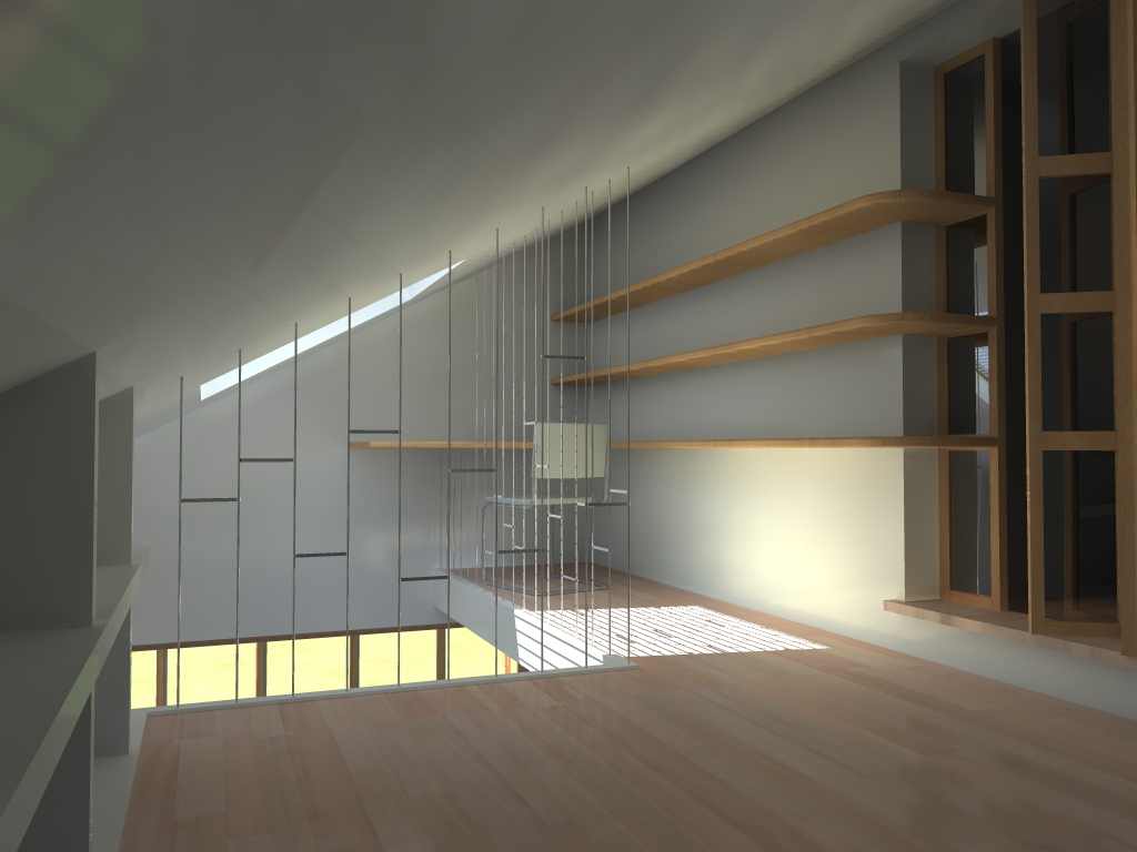 CGI of a mezzanine
(click to enlarge)
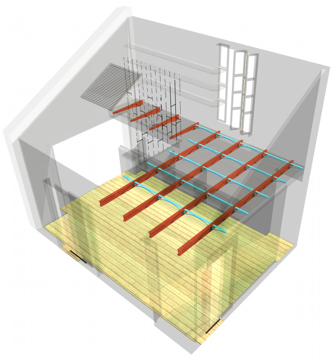 Axonometric X-Ray constructive analysis of the same mezzanine
(click to enlarge)
Over the past few years, we’ve been witnessing a genuine increase both in the performance of 3D CAD software and in the skill and talent of young architects. Computer generated imagery is becoming more and more abundant in today’s architectural design market. This is also partly due to the fact that clients tend to demand this kind of high-end service more frequently. Those images could be easily sent by email to friends and family for them to give their opinion.
4. Second client validation and construction permit: 1/100 – 1/50 scale. No architect dares to hope that his client will be 100% satisfied with his initial design. Often, there are many modifications and changes, but the path is clearer and the team is reassured once the concept has been accepted. Now is the time to get “down to business” The design team’s work now, is to get the project approved by the authorities for construction. In most western countries, the construction permit drawings are handed in 1/50 scale with an “in-site” integration of the building (CGI again…) Like the following example:
 In site CGI insertion (click to enlarge)
Although in the first client validation phase, CGI is not mandatory, most competent authorities demand one, so that they could make an idea of the project’s integration impact on its surrounding environment.
5. Execution plans: Detailed 1/50 scale and some parts in 1/20 or 1/10. Finally! The project was approved by both client and the authorities now comes the final part of architectural designing where “all hell breaks loose” – This is usually where our poor design team discovers that the plumbing doesn’t perfectly fit with the foundations and that the window they chose for the hallway is no longer manufactured because the draftsman used an outdated catalog from 1988… The plans are sent back and forth to the contractors and engineers for review and there is much rejoicing. It’s during this phase that most of the materials and architectural elements are specified. In some places, plans are not enough and architects actually write down – for every room and corridor – a full detailed textual description of all of the amounts and materials. At this point, the client tends to develop nostalgic feelings towards his initial budget and the days his local bank manager actually smiled at him…
6. Construction. Oh dear, now we actually have to build all that??
IMPORTANT NOTE: These 6 phases are generalized. There are lots of variations. The process I described fits the description of building for a private client. Building for governmental or other institutions is somewhat different than the described above. I’ll be happy to detail it in the comments or future posts if there’ll be a demand.
Where do YOU come in?
Well, it depends on what you are manufacturing:
- If it is software for architects you probably want to find a time somewhere before phase 3 and after phase 5 – Architects will be much more receptive to new technologies when they are not on a tight deadline.
- If it is design furniture, your golden hour is during phase 2 when the architect aims to seduce his client.
- If you’re a manufacturer of doors, windows, flooring, or any other Parametric BIM object – It’s probably best to intervene during the 5th phase. Actually, if architects know of you – they’re most likely to contact you themselves.
Usually, architects work on several projects at the same time, and their phases do not overlap, how can you make sure you are reaching the designing team at the appropriate moment? Who should be your contact person? How do you find him or her? – All that and much more – in the following chapters.