
Case Study #6 – Alucobond
Polantis presents the BIM approach of the world leader in aluminum composite panels. Discover the Alucobond Case Study: behind the scenes of the creation of the CAD and BIM catalogue.

The BIM approach
Alucobond was introduced to Polantis in 2013, and its BIM (Building Information Modelling) approach was special because it was exceptional as it was developed in two phases.
A decision was made to create a model for the manufacturer’s panels, by first developing shaders or textures. The objective was to enable users to view the aesthetic qualities of the Alucobond products in the work that they were designing at the time.
In 2016, with many shaders produced and with Alucobond better understanding of designers’ interest, the teams opted for the creation of three facade panels.
What’s the advantage of downloading a complete Alucobond system? It lies in the ability to integrate a panel into a digital model and combine a texture with it in order to:
- Take advantage of the opportunity to integrate a digital model system: automated calculations, synthesized product information, etc.
- Take advantage of a perfect rendering to allow the designer to « sell » the final work
Throughout the modeling process, Polantis found in Alucobond’s German teams an attentive interlocutor that was careful to respond to the expectations of the user.
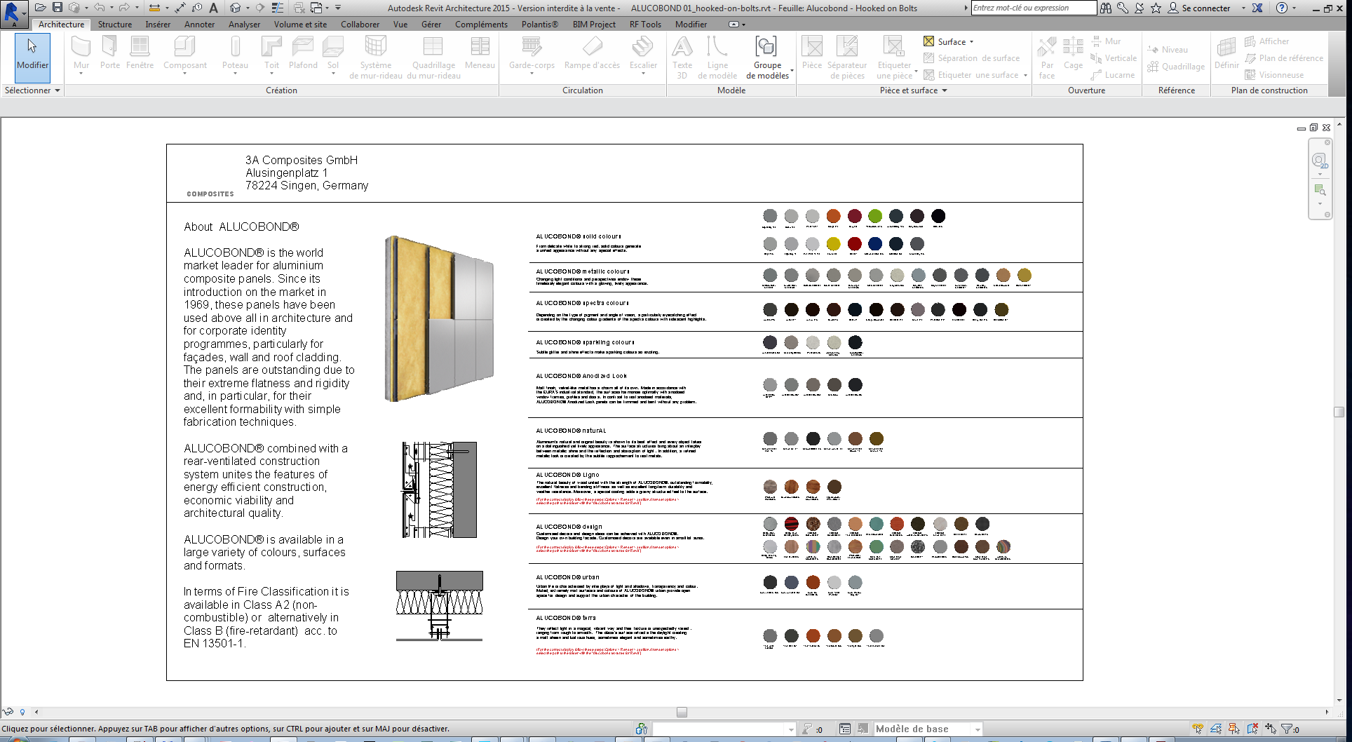
The composition table of the « Hooked on bolts Suspendend Tray Panels »: systems and shaders are included
Shader modeling for Revit
In 2013, the chief architect of the Alucobond project at Polantis visited the Alucobond factory in Singen to learn about the history of the manufacturer, its manfacturing processes, and the attention paid to the quality of the designs created for facades.
Once production began, back-and-forth communication between Alucobond and Polantis were necessary for adjusting the level of realism and specificity of the colors in order to achieve a perfect rendering. The shader modeling was created thanks to the catalog of refererences and the samples scanned which were provided to the architecture team by the manufacturer.
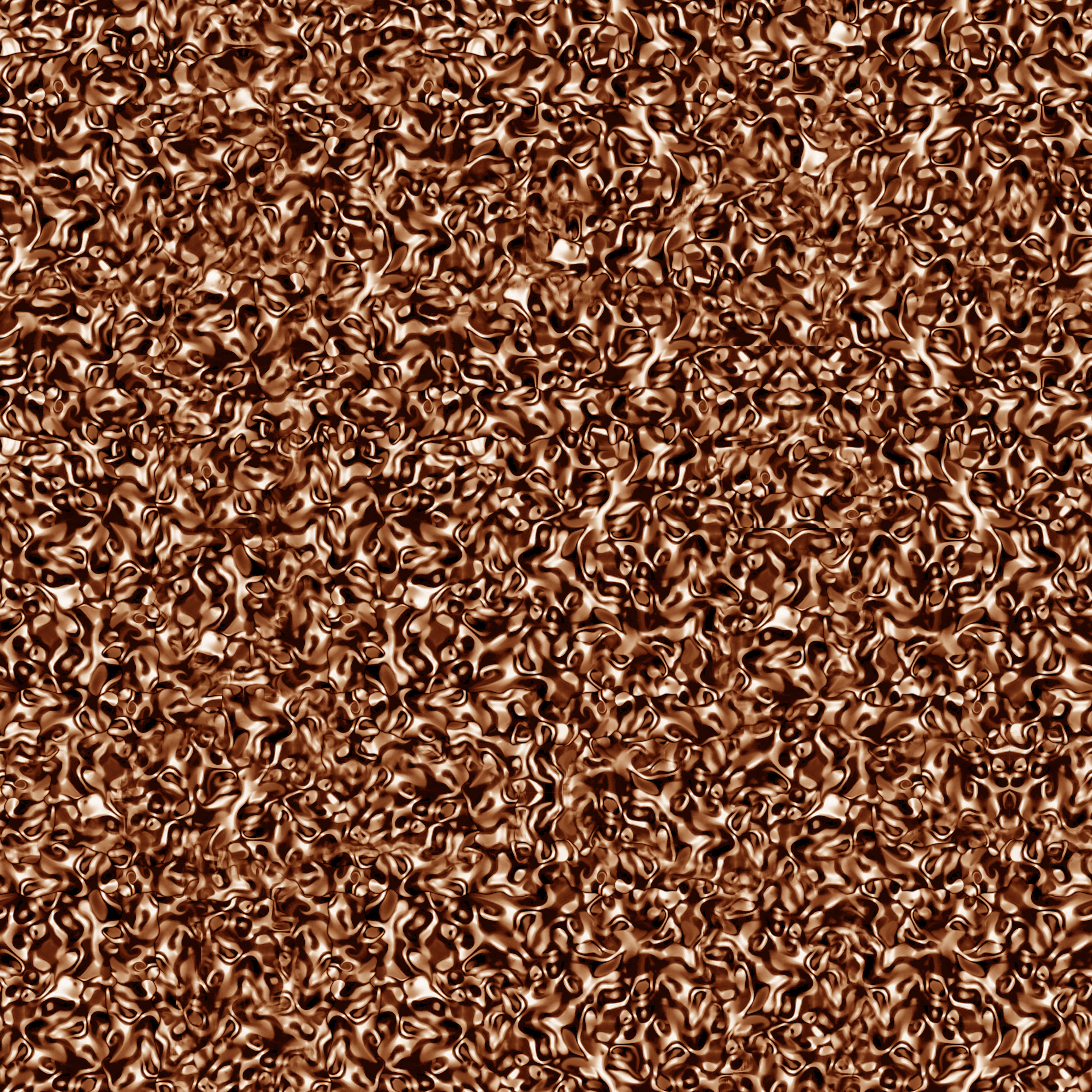 Alucobond Gravel D0011 texture
Modeling of shaders for Archicad
In 2016, Alucobond asked Polantis to develop a range of textures first created for Revit for the ArchiCAD software.
The team dedicated to the Archicad program then took on the project. It was necessary to go back practically to the starting point to recreate each of the 94 textures: it was possible to retrieve the elements since they were RAL, the scale of the textures, and the dimensions of the designs.
Modelling the most elaborate textures was done from the Archicad rendering engine: the CineRender. In the same way as Revit, the level of difficulty varied according to the complexity of the texture: metallic aspects, fresnel effects, reliefs, etc.
The advantage of ArchiCAD is that CineRender is a very high-performance rendering engine, so the user can stay within the software and observe the aesthetic qualities of the product, without having to open up a third-party software program, so it’s easier to view the textures.
Upon its involvment in the second phase, the team in charge of modeling in ArchiCad suggested to Alucobond to allow users a download by packs: several shades of the same line could be downloaded in one go.
This simpler operation was adopted by the modelling team for Revit.
Modeling of the panels
Three years later, with the textures modeled, Alucobond asked Polantis architects to work on the « background », or rather, « backstage ». How many panels, how many slabs were behind a texture applied onto a given surface? What was going on behind the texture?
Modeled facades are a real time-saver for designers, who can try out several possibilities in the drafting phase, with the use of an automatic tile layout calculation and the chance to visualize the applied colors.
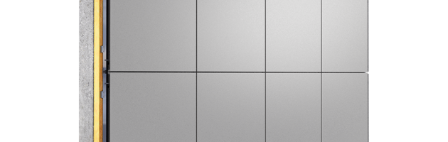
 The panel Hooked on bolts Suspendend Tray Panels
First, the team examined the level of desired details, and it was agreed that three would be developed:
- The 1st level is a simple representation of a facade panel: in terms of the file weight, replacing a generic wall with an Alucobond panel came out to the same thing. Smartly, the Alucobond wall automatically calculates the number of panels as well as the cut-outs for the doors and windows.
- The 2nd level is a more realistic representation than the first level, but it doesn’t go into exhaustive detail. The goal? Work on the interaction with other elements of the model. This level also allows for the combining of several Alucobond textures: each panel can be associated with a color or a different design for maximum creativity.
- The 3rd level is a very detailed representation of the system. The bearer system, screws, details regarding proofing, and component links are shown. This object should only be used to understand the construction system, and it should only be used for a close-up of the product.
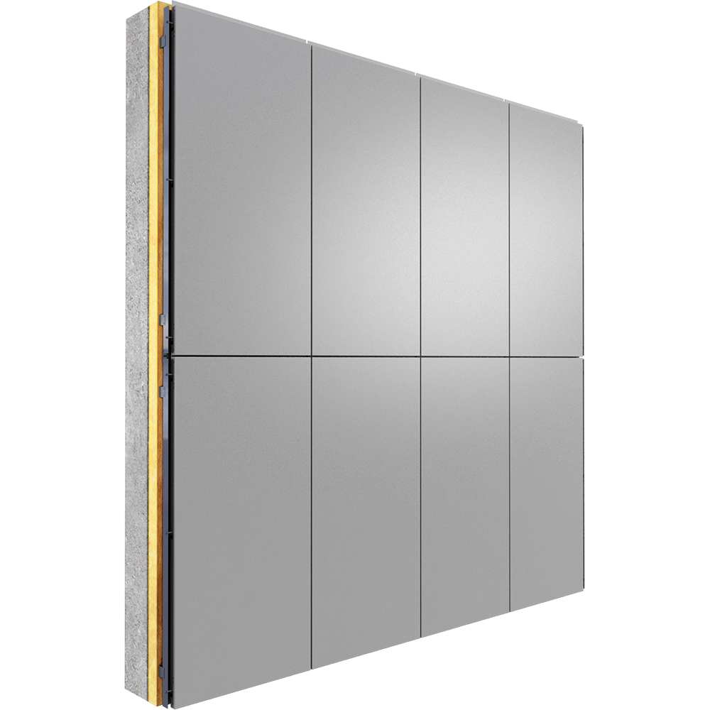
Four layers can be distinguished by modelling the panel with the highest level of detail:
- The bearing wall: masonry, concrete, metal, etc.
- The proofing
- The aeration layer
- The Alucobond panel with the fastener to be used for the proofing
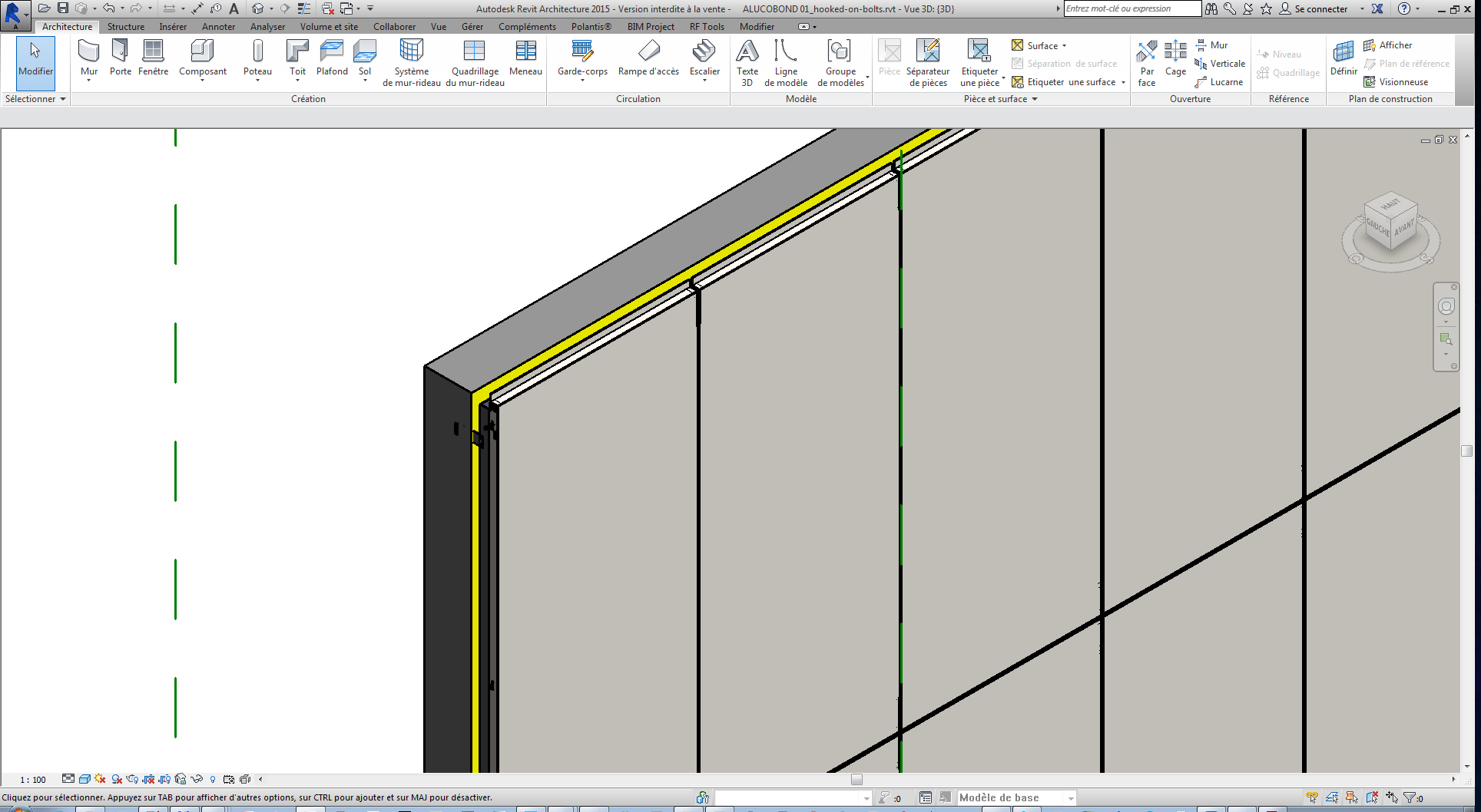 The 4 layers of a panel (3rd level of detail)
Modeling of panels for ArchiCAD
In order to offer its BIM solution to a maximum number of users, in 2016, Alucobond also chose to offer a range of its systems to ArchiCAD.
The architects in charge of the project therefore produced:
- A simple version of the panel on which the textures developed could be applied, with automatic compliance with the scale: the panel reacts in ArchiCAD as it would react on the construction site. This level of detail does not allow for alternating textures on a single panel, and it is not possible to select panel parts independently from one another.
- A curtain wall version which will allow application of different textures onto a single panel and prepare a gridding for the length and width of each panel. Parameters can be set for the entire wall.
It is interesting to note that in ArchiCad, the BIM’d product is considered a parametric object while in Revit, it is considered a system object.
The desire to serve a maximum number of specifiers
The two software programs do not at all have the same functions at all, therefore it was impossible for the Polantis teams to think about the modelling of Alucobond products in the same way. The two teams worked independently from one another. Far from harming the production, these reflexions allowed the teams to obtain a global view of the project, and to innovate in order to underpin the Alucobond BIM approach.
Over the past months, on Polantis, downloads in BIM formats are distributed between formats as follows:
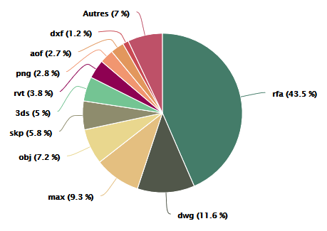
Revit totaled 47.3% of the downloads, so it is common for manufacturers to start their BIM approach by having their product modeled on that software. However, modelling in ArchiCad is more and more commonly requested by manufacturers.
Case Study #5 – Rector
Polantis presents the BIM approach of one of the major players in the concrete materials manufacturing market. Discover the Rector Case Study: behind the scenes of the creation of the CAD and BIM catalogue.
![]()
The BIM approach
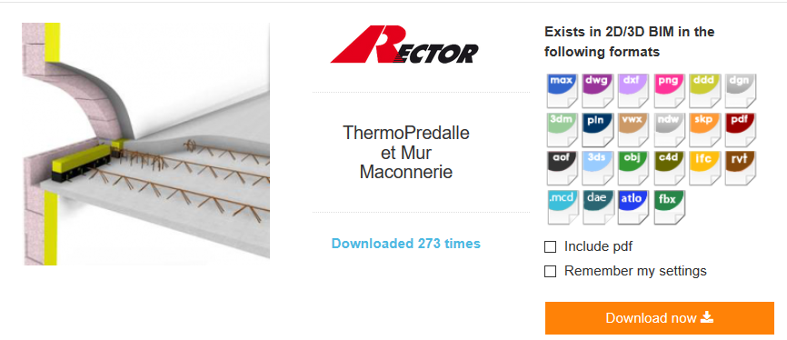
In September 2015, Polantis put the Rector CAD and BIM products online: the « ThermoPreslab and Masonry Wall » and the « ThermoPreslab and ThermoPrewall ».
What makes the manufacturer’s products unique? A part of the system is designed in the factory (with integrated iron framework) and the concrete part is poured at the construction site.
The outcome? Easier assembly and incomparable construction quality, specifically with very strong thermal performance (no thermal bridges).
For Polantis, modeling Rector’s systems was a challenge: how do you design a multilayer object and ensure that it is perfectly adapted to the project?
Test 1: « the super product »
With Rector’s full collaboration, the team of architects in charge of the project launched a study in order to determine the best way of understanding product modeling.
First, it was understood that the walls and flooring would be treated in the same way because the construction system was the same.
Next, the teams decided to create a super product. The iron framework would be distributed automatically in the part treated: this was the insurance that the product would be represented from « the inside » with all of the elements that constitute it.
However, very quickly, the team discovered several obstacles to modeling this product.
The iron framework, which became parameter-adjustable, could not be properly integrated with complex-shaped parts and was not adaptable to all types of surfaces.
What’s more, the Rector iron framework integrates into two principal layers of the system, which could not be parameter-adjustable in Revit.
Lastly, the question was raised regarding the premier user of the products: an architect did not have any utility to exploit this super product which, in addition to being slow to load in the model, included information that was more useful in design offices.
The study, therefore, revealed that this product was too elaborate.
A multilayer system
In parallel to the meeting with Rector, Polantis began to collaborate with Siplast (a specialist in impermeability). As the two products are successive layers of insulation, the reflection for modeling the Siplast products was also useful for reflections on Rector products.
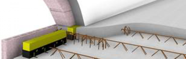
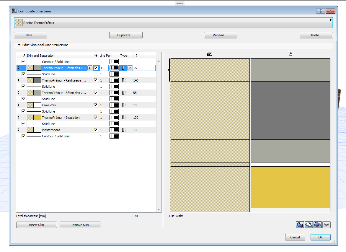 The ThermoPrewall layers
Similarly, the agreement was to design a .rvt format system in which these layers would be represented: the insulation layer, the concrete layer, etc. The iron framework would no longer be represented on 3D elements, but on 2D elements and on other visuals provided with the product when it is downloaded.
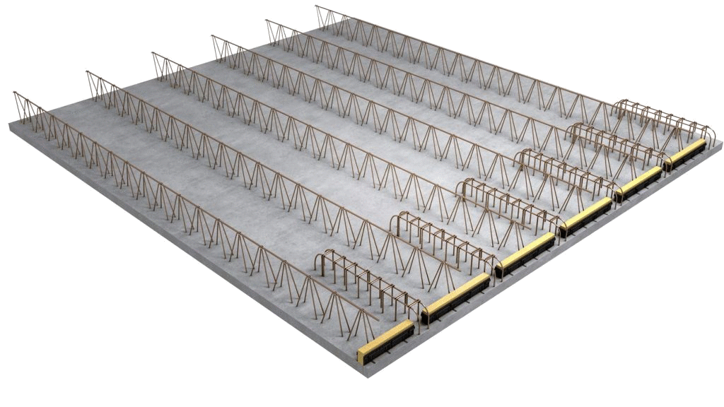 A computer image that shows the layout of the iron framework
The difference between the .rvt format and the .rfa format
On a Revit project, the model is made in .rvt: it brings together all the elements of the project; in some respects, it is the anatomy of the building. The .rvt format model includes the nomenclature, materials, parameters, geolocation…all possible information. With all this information included, it is possible to communicate with the other trades involved in the design & build chain.
An object in the .rfa format belongs in fact to a Revit family. These are objects that can be taken and then simply moved, like a window, a chair, or a lighting fixture. We talk about them in terms of family because there is an organization between such objects: some are parents while others are the children or grandchildren.
The major interest in having designed the Rector system in the .rvt format resides in the fact that it can, unlike the .rfa format, contain information in the form of text or image files.
The « I » in BIM stands for Information
For example, modeling an .rvt object lets you integrate the iron framework layer into the system, not in terms of its geometry but in terms of its information.
This proved to be particularly necessary because, for example, if it was integrated into the product in the form of a layer, without, however, its parameters set by the Polantis teams, it would be up to the architect to decide how to place the iron framework, thereby involving the architect’s liability in the event of a calculation error.
The importance of the information provided is at a maximum in the case of the Rector BIM objects: in order not to overload the digital model, the product is visually « lightened » and represented more simply, but all of its qualities, its placement mode, unique points and performance information, and standards are associated with the object at the time of downloading.
A « hub » object
In order to best exploit this informational dimension, the agreement with Rector was to conceive of the modeled systems as « hubs »:
- « fixed » data was added into the object parameters.
- Computer images were created to help understand the « inside » of the system and understand how it is placed in the construction site.
- Data that may evolve were added in the form of a URL link that leads to the Rector site, and product information is continually updated: regulation, standards, label, performance, economic comparative information, etc.
-
- The composition table provided with the object included all of the unique points that allow for best product placement: the unique points designed by the Polantis teams (and validated with Rector) are intended to be copied and pasted by the object user.
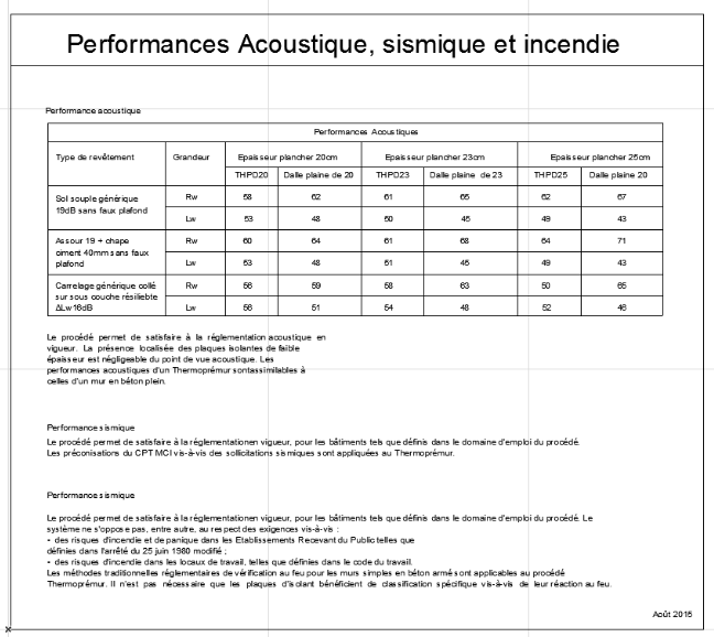
Information on acoustic, seismic, and fire-resistance performance
The BIM for all the actors involved in construction
Ultimately, this « hub object » proposed by Rector works to serve all the users of the Design & Build chain perfectly. Here is a list of the actors who are concerned with BIM objects:
- Thermal BEs
- Economists
- Architects
- Promoters
- Construction Companies
- Acousticians
- Inspection Offices
To be useful for an ever growing number of persons, the Rector BIM objects are also available for the ArchiCAD software program. The objects modeled for Allplan are currently in production by the Polantis teams.
We suggest the following articles:
Case Study #4 – Wienerberger

Polantis presents the Case Study of the Wienerberger’s BIM approach: behind the scenes of the creation of CAD & BIM textures of the leader in terracotta.

The objective of the BIM approach
In October 2012, Polantis put online 29 brick textures designed for Wienerberger.
This incomparable specialist in terracotta began a BIM approach for a large panel of products: from traditional colored brick to more elaborate effects, and naturally-colored materials.
The end purpose for Wienerberger, a leader in terracotta, was to confirm its leadership position by putting itself at the cutting edge of innovation.
The issue for the team of architects in charge of the project at Polantis was as follows: with the wall covering being the first view of a project, it was imperative to reproduce with complete accuracy the aesthetic properties of the Wienerberger products.
The documentation provided by Wienerberger
Wienerberger provided Polantis with several sources with which to work: sometimes the photograph of a part of a wall, sometimes the photograph of an area of bricks superimposed but without joints, and other times views of the building in perspective.
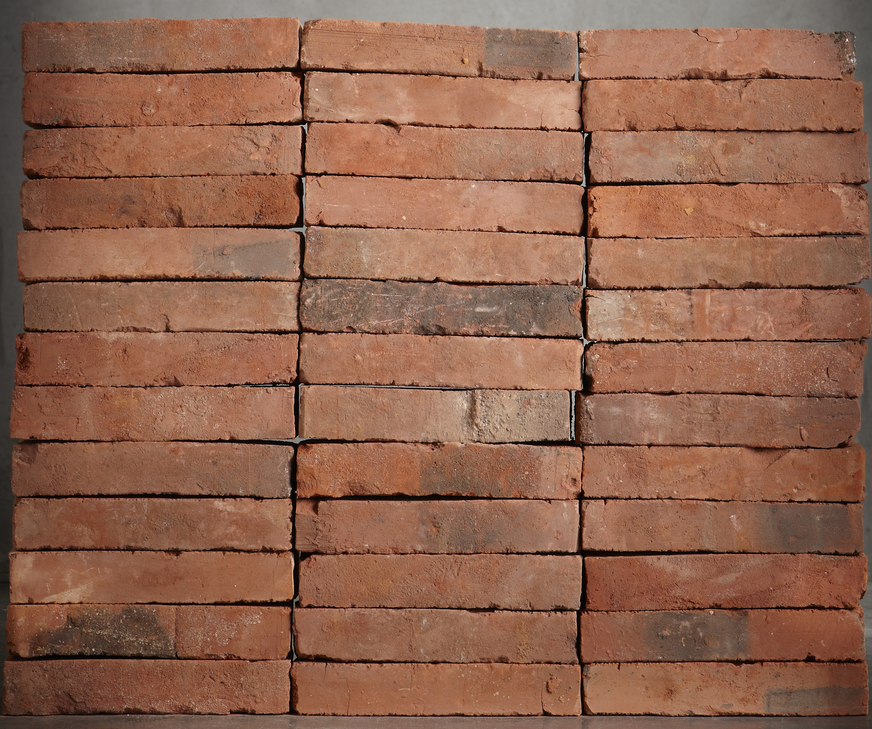 The « Lof Red » from Wienerberger
The first action taken by the team of architects in charge of the project was to cut out and isolate each brick present in the photograph to keep its specific qualities in order to continue to showcase the richness of the material.
It was also necessary to « flatten » the views in perspective so that the user could perceive in total specificity the sizes and formats of the bricks modeled.
The 3D representation
There are four types of BIM objects: the simple object (for furnishings for example), the parametric object (for a product with variable dimensions), the system (for a product composed of several elements and variable dimensions) and the texture (for wall or floor covering, for example).
Wienerberger products are textures: what was needed was to represent a wallpaper that would be applied to a given geometry.
Because the bricks could not be modeled and assembled one by one, since this would be too fastidious, the architectural team designed an infinite texture that could be applied with a click on any wall whatsoever.
An infinite texture
An architect who wishes to apply a given texture could be satisfied with cutting and pasting an image of a « brick » taken randomly from an online catalog: the repetition would be noticeable and the resulting effect would not be natural.
 A texture that is simply « cut and pasted »
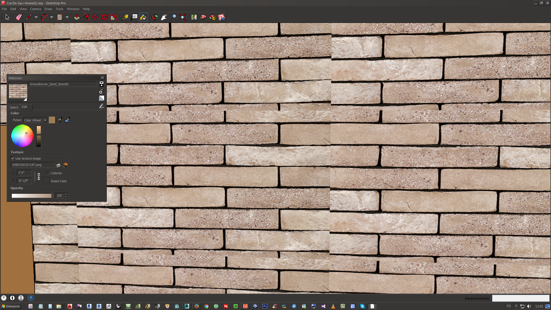
The Polantis teams worked in Photoshop in order to adapt the texture in such a way that it would react like a real assembly of bricks.
The shader, a combination of layers
The term « shader » is used when there is a combination of several shaders.
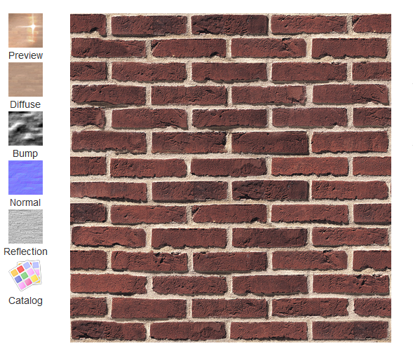 The 5 elements that compose the Wienerberger Purple Agora shader
A well-made shader always combines 5 elements:
- « Diffuse »: this is a single layer which indicates to the software which color is to be applied to the object
- « Bump »: is the shader relief. Thanks to the Bump layer, the texture is realistic. This layer is composed of dark areas that represent hollows and clear areas that represent the surface.
- « Normal »: this is a special layer that only the software (Sketchup, 3DS Max, Revit, etc.) can interpret. It also contributes to the realistic effect. And it allows the user to simulate details and recreate irregularities in the material. This is a special filter that comes software specialized to achieve special effects: the effect is called « normal mapping ».
- « Reflection »: the material reflection, meaning its « smooth » effect, is simulated using a filter that is complementary to the « normal » layer: the more white there is, the lighter is sent back to the eye. This effect is most important to achieve a smooth and contoured appearance.
- « Specular »: specularity determines the clarity of the reflection according to Newton’s theory. It also contributes to making the texture more or less smooth and modulates the level of brilliance of the material.
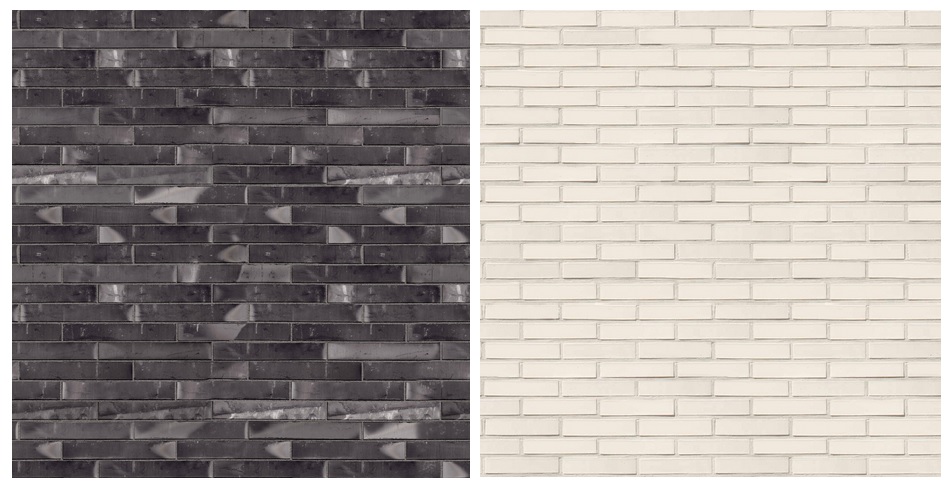 The « Linnaus Etouffle » covering on the left is smoother and more brilliant than the « White Earth » covering on the right.
On the Wienerberger page presented on the Polantis platform, all of these elements are presented next to the shader so that the user can have a glimpse of what is found in the .zip he or she downloads.
This information allows prescribers to obtain in details how the shader to be applied to projects is composed.
The final informational element along with the shader is a view from the Wienerberger catalogue: this will allow the user to note the absoluteness of the resemblance between the given file and the real object.
Exchanges with Wienerberger
The work of the Polantis architects was validated after a meticulous study made by teams working with this specialist in terracotta. The attention given on the part of the manufacturer was above all devoted to the realistic effect of the shaders. Some elements had to be modified:
- Some colors were not faithful enough to reality: particularly the pigmentation of ocher-colored bricks which needed to be more irregular
- The junction between the bricks of certain shaders was overworked: this did not showcase well enough the rustic quality of the product
The architect and the client
These points needed a high level of interest because the architect needed the project presented to his client to be highly faithful to reality, so the image and the rendering were prioritized.
This fidelity allowed the client to identify with the result and validate the project more easily.
In the case of BIM, it is commonly said that the digital model allows one to « build before building », so to present an object with realistic aesthetic qualities helps the architect and his client to develop more constructive exchanges.
Case study #1 – Enveloppe Métallique du Bâtiment
Polantis presents the Case Study of Enveloppe Métallique du Bâtiment. Focus on the creation of the syndicate’s generic objects.
![]()
The main purpose of the BIM process
In March 2015, Enveloppe Métallique du Bâtiment (ex. SNPPA) met Polantis.
The main purpose of this syndicate was to allow its members to see their products integrated into projects created in BIM. To do this, Polantis had to model a selection of generic products among those most currently used in construction.
The choice made by the Enveloppe Métallique du Bâtiment was based on 58 construction systems: cladding, panels, covers, etc., and they wanted to be provided before November, 2015, for the presentation at the World of Construction (Batimat).
A unique client and BIM approach
Then Polantis’ teams asked themselves: « What information should we submit to the user for generic products? », « How can a synthesis of several products with many different technical qualities could be done? », « How to create objects intended to meet the needs of several manufacturers, and sometimes even competitors? »…
A revealing pilot project
As a pilot project, a first test object was created to check this process: the Polantis team of architects modeled a clad on Revit and realized its composition table.
This object was created with some difficulty. In fact, the team worked using documentation that was very extensive, perhaps too extensive, and presented diagrams in which there was no a legend, no scale, nor dimensions.

Horizontal double skin clad: the diagram of an angle
The need for a specific and hierarchically laid-out documentation
Polantis then asked Enveloppe Métallique du Bâtiment for more documentation: Autocad files, detailed diagrams, factory plans, etc. This was a request for specific and hierarchically laid-out information that the manufacturers could have easily provided but that the syndicate, unfortunately, did not have.
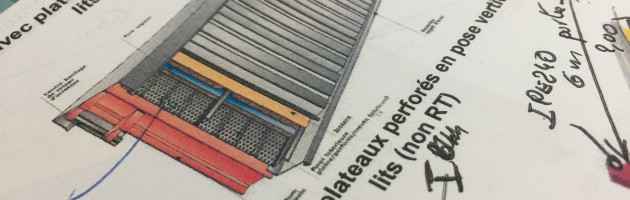
With the help of Polantis, a lot of work was then undertaken by Enveloppe Métallique du Bâtiment to gather together the documentation, to sort it, to annotate it, and to organize it. For each product, the syndicate had to provide an informational sheet completed with designs where all fundamentally important information appeared.
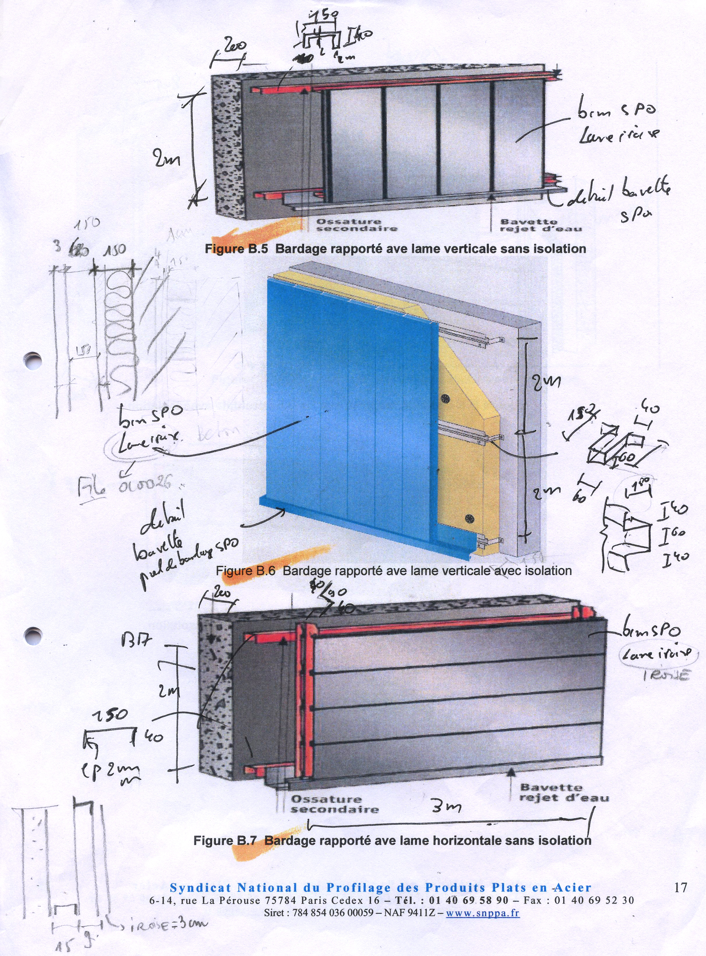
A document provided by the syndicate
To ease this process, the team of architects and the expert from Enveloppe Métallique du Bâtiment made the decision to work together.
Half-day meetings were held bi-monthly. The work was organized according to the opposite steps. First, the expert corrected one or two products, and during corrections, he explained the construction principle of the type of products in question. This allowed the architect who was project lead to understand the product better and to realize it. This cooperation also allowed her to understand what she needed to hide, or on the contrary, what she needed to explicitely show. After the session, similar products were treated independently and sent back to the expert for validation. The following session was about another category of products.
The expert also took advantage of this work to understand the possibilities and the limits of the CAD and BIM software programs on which the team of architects was working. Each person took away from these exchanges more competence about the project, and also a better understanding of the professional task.
Finally, beyond the architectural work, this collaboration between the syndicate expert and Polantis architects was important since there was no industrial in charge of its products. Thus, the presence of the expert was needed for him to be responsible of the products designed, to check their faithfulness to the reality, and to attest that each member of the syndicate was represented in these generic products.
Thanks to this checking phase, Polantis was able to guarantee the satisfaction of the members.
Product information
In BIM (Building Information Modeling), one element is Information. A BIM object is partly the visual representation and manipulation of the model and partly the information (standards, material resistance, thermal performances, etc.).
This information linked to the product informs everyone, from the designing to the building maintenance: it can be consulted by each of the persons concerned.
Composition tables, unique points
First the specific situation in which the products can be integrated in building phase were treated . The purpose: the final user could then have access to a solution for most of the uses he or she may have once the product modeled.
A composition table
This stage was very important for the proper usage of the products. Indeed, designing these unique points with such precision allowed them to better perform what they were there for: to be directly embeded into the plans of the CAD and BIM software programs, at scale to understand which detail size is designed, and ensure compliance and coherence, thanks to the organization of legends.
Mastering the information
Regarding the information contained in the products, Polantis shared the expectations of the final user (the architect, the designer, the engineer, etc.) with the syndicate. At the moment of design, what information should be provided to take the best advantage of the BIM? Enveloppe Métallique du Bâtiment teams were able to respond by completing an Excel file submitted to them.
In addition, and upon request by the syndicate, users should find this information attached to a diagram outside of the digital model. According to Enveloppe Métallique du Bâtiment, by using this, a user who does not master a BIM software program could ensure that the information was properly linked with the product.
The organization of the information
To better explain the product to the user, the syndicate also thought about how the information was organized.
For example, to be as learner-friendly as possible, a color code was submitted to the Polantis team of architects to enable the user to better visualize the construction principle of each point:
– Red for fastenings,
– Blue for spacers,
– Green for finishing parts.
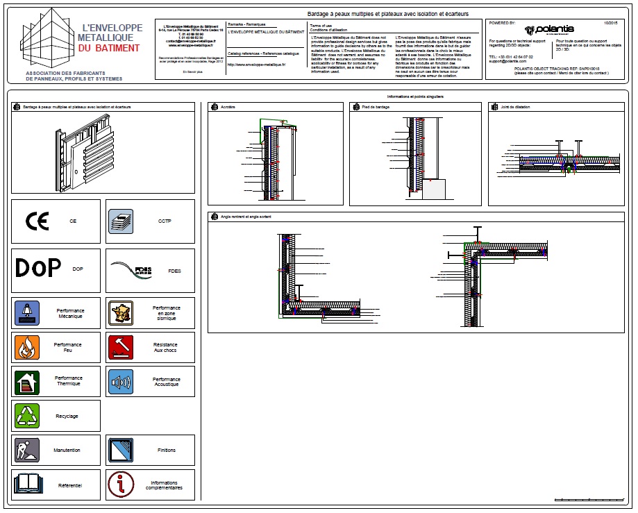
For the same reason, the pictograms below were designed to present regulatory information about the product: the user should be able to click to directly access the site of Enveloppe Métallique du Bâtiment.
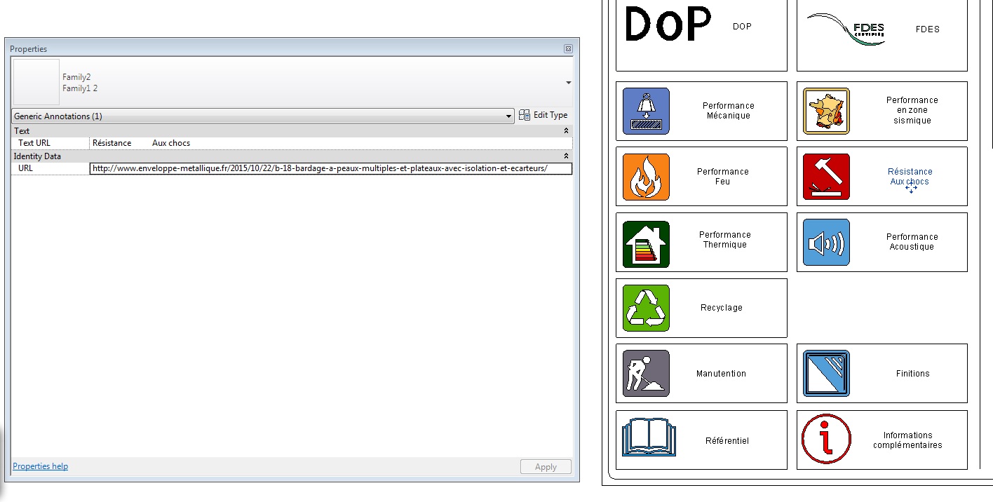 The software indicates that the « Shock Resistance » pictogram contains a link that can be consulted
3D representation
There are four types of BIM objects: texture (for wall or floor covering, for example), the actual object (for furnishings, for example), the parametric object (for a product with variable dimensions) and the system (for a product composed of several elements or with variable dimensions).
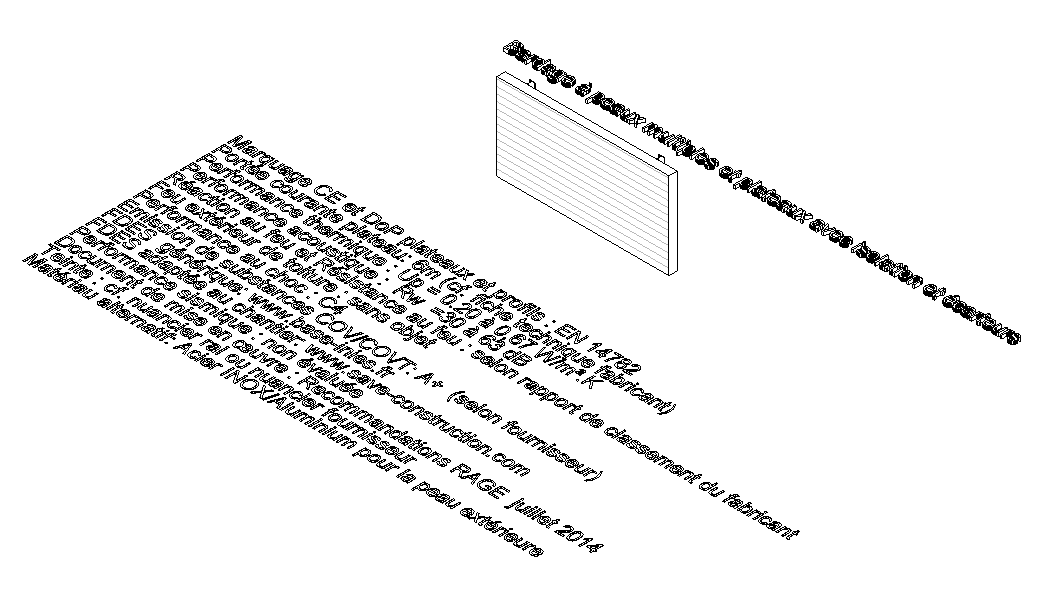
Based on the request made by Metallic Envelop and following a preliminary study, the Polantis team of architects chose to create different systems. A BIM system has the advantage of being able to integrate into the quasi-totality of projects and digital models, and it offers a remarkable degree of flexibility.
The 3D product models were worked on in CAD with maximum 3DS for a rendering that perfectly matches the reality, with an extremely well-developed control process, all the way up to a study of the dowels and fastenings.
The product’s faithfulness to reality is also perceived through its respect to regulation. In the same way that the product is designed according to regulation, its digital avatar complies with standards. For example, for the type of cladding below, construction regulations (interaxial between two IPEs) or types of insulation (rockwool or polyurethane) combined with the product needed to be modeled.
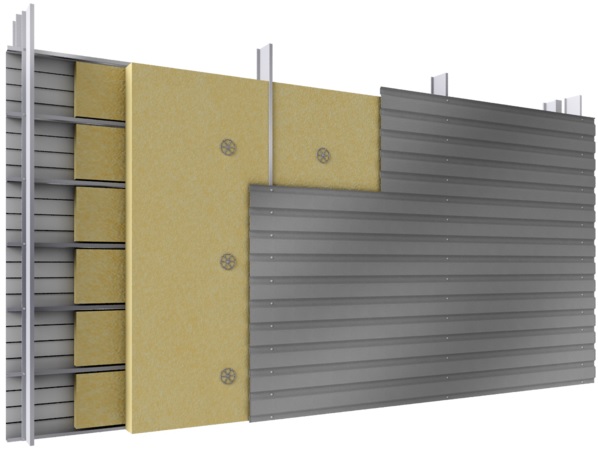 Double skin steel cladding
The question of what is visible and what is invisible was also raised: what did Polantis need to show to the user? Enveloppe Métallique du Bâtiment chose to show the whole composition of the product, showing the various elements that constitute the product.
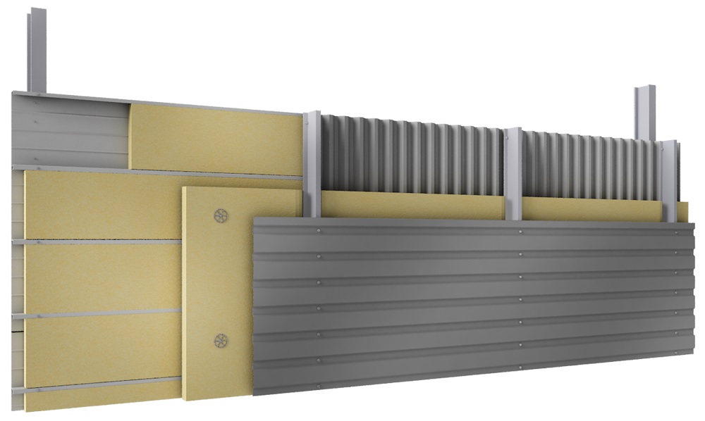 Multiple skin cladding
For the example above, you can distinguish from left to right:
- the integration of the rockwool insulation in the cladding board,
- the pattern of dowel fastenings,
- the proper representation of the insulation binding,
- the proper setting of the cladding on the spacer,
- the finish and placement of the product rendering.
Therefore, the task was to turn a real product into a digital system, going from abstract to digital.
A rewarding collaboration
In a nutschell, the 58 products that are now available were designed by combining the expertise of Polantis architects and the will of Enveloppe Métallique du Bâtiment to fully address its members’ needs.
The ultimate proof of the success of this operation: Enveloppe Métallique received the Industrial Silver BIM during the « BIM d’Or », awards ceremony organized by Le Moniteur magazine.
Today, the BIM process is still ongoing: Enveloppe Métallique du Bâtiment teams and industrial members are working with Polantis to improve these generic BIM objects thanks to the feedback given by BIM professionals and experts.